
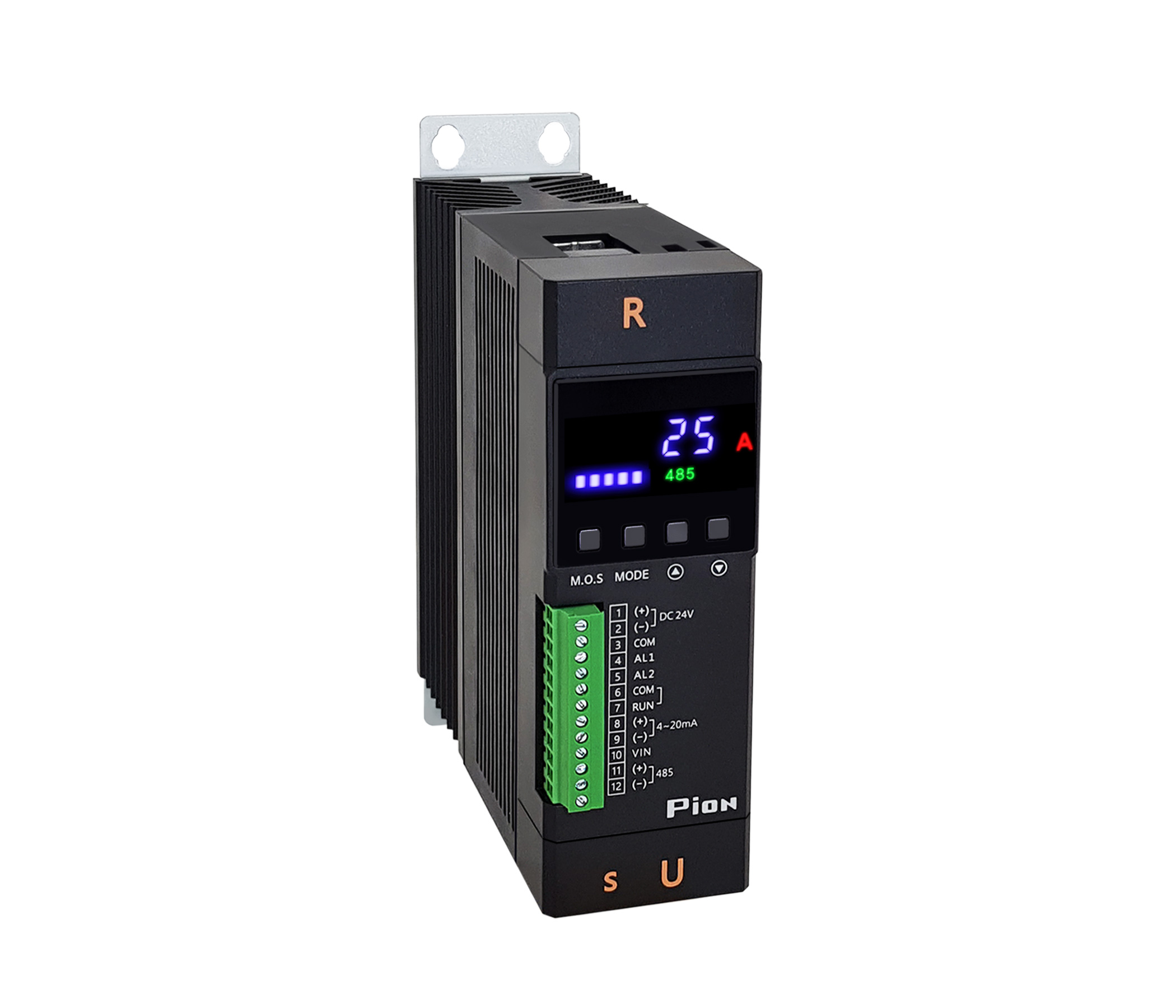
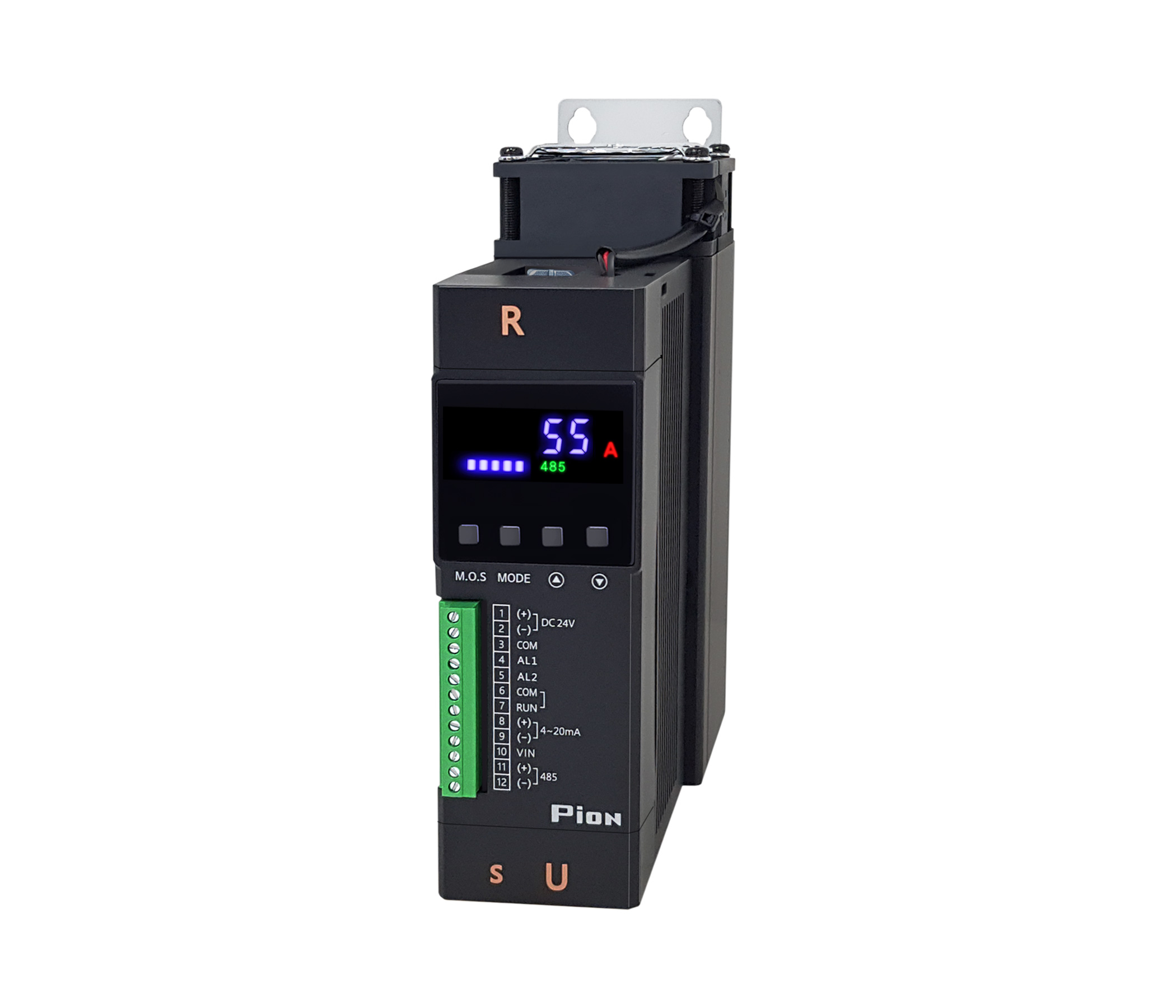
1-Phase Lite 25A~75A
A RIGHT THINK FOR QUALITY - PION SERIES
본문
MODEL
PION-L1W-025-xx
PION-L1W-033-xx
PION-L1W-055-xx
PION-L1W-075-xx

SPECIFICATION
A RIGHT THINK FOR QUALITY - PION SERIES
For detailed information, please download the "User Manual" below and refer to it.
| CATEGORY | SPECIFICATION | |||
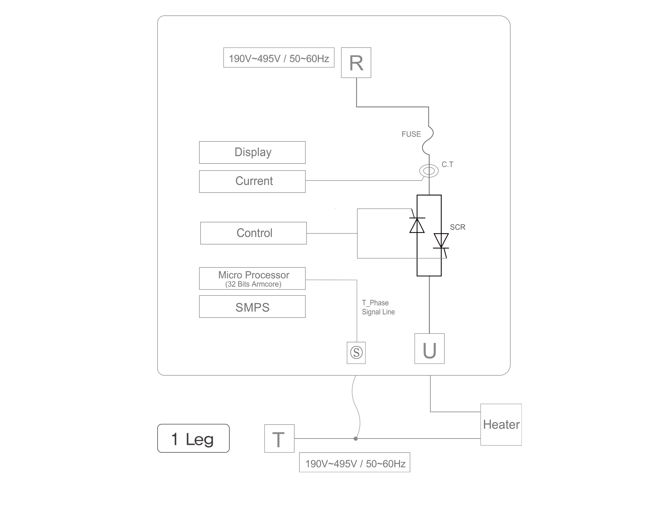
Power supply
|
220~440VAC (Min190~Max 495 / R.T Input : Free Voltage) |
|||
Related
|
25A, 33A, 55A, 75A |
|||
Operation
|
50/60Hz (Automatic discriminating) |
|||
Control |
Phase control, Zero crossing control, Combination control (phase + zero crossing) |
|||
Control |
4~20mA, 1~5VDC, 0~5VDC, VR10KΩ, MODBUS (ASCII/RTU) |
|||
Load
|
Heater coupled load (Phase / Zero crossing), Inductive load (Phase) |
|||
Minimum
|
Over 1A |
|||
Output |
0~99% |
|||
Output
|
Signal (4~20mA etc.) control :12Bit
|
|||
Environment |
Humidity : 20~90% (without condensation) Surrounding Air temperature : 0~50℃ |
|||
Cooling
|
25, 33A : Natural air cooling type
|
|||
Dielectric
|
3,000VAC ~50/60Hz for 1 min |
|||
Insulation
|
Power : Case 200MΩ (at 500VDC) |
|||
Control |
DC 24V (25, 33A - 1.5W / 55, 75A - 3.2W)
|
|||
Alarm
|
Alarm1,2 Relay output : Over current, Overheating warning, Blown FUSE, Thyristor failure, |
|||
Basic
|
|
|||
Optional
|
• Current limit (voltage feedback)
|
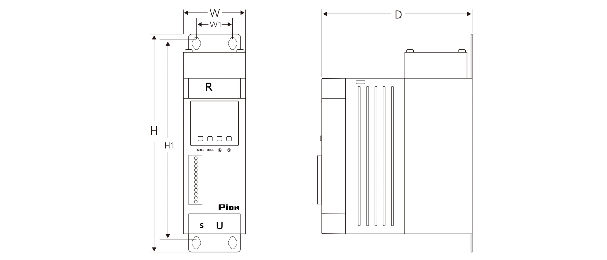
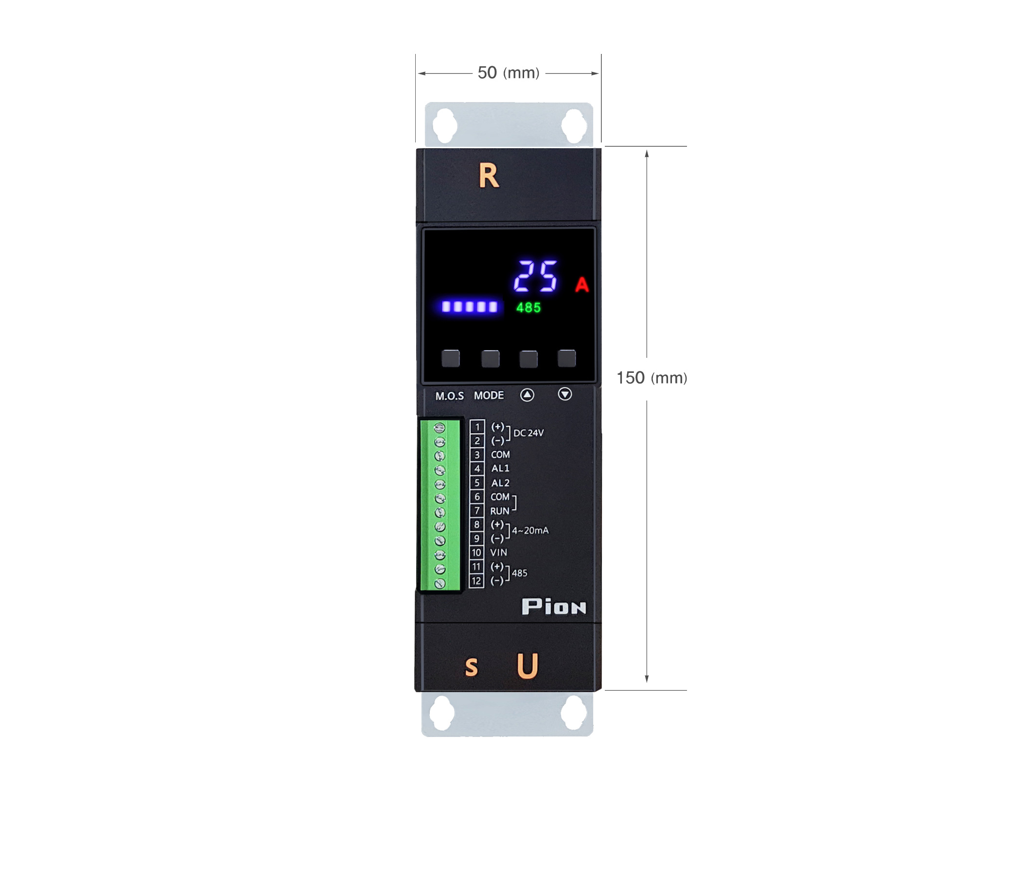
DIMENSIONS
A RIGHT THINK FOR QUALITY - PION SERIES
For detailed information, please download the "CAD drawing" below and refer to it.
| Capacity (A) | W | H | D | W1 | H1 | Interval (T) | Weight (kg) | Attachment bolt |
Main Power bolt |
25,33 |
50 |
185 |
140 |
30 |
167 |
20 |
1.0 |
M4 |
M6X15 |
55,75 |
60 |
210 |
145 |
35 |
192 |
20 |
1.3 |
M4 |
M6X15 |
| Capacity (A) |
25,33 |
55,75 |
| W |
50 |
60 |
| H |
185 |
210 |
| D |
140 |
145 |
| W1 |
30 |
35 |
| H1 |
167 |
192 |
| Interval (T) |
20 |
20 |
| Weight (kg) |
0.96 |
1.3 |
| Attachment bolt |
M4 |
M4 |
| Main Power bolt |
M6X15 |
M6X15 |
Formula of an electric current amount change According to heater capacity
Actual loading capacity (A) = Result not "x 1.3", Design loading capacity (A) = Result "x 1.3".
Our rated capacity is on condition 25 degrees at room temperature & Rated voltage,
So Please put your
capacity calculation Considering the Field situations (Temperature, Input Voltage etc) when choosing a model.
-
3 Phase
Resistive load=
Heater (W)
× 1.3
1.732 × Voltage
-
3 Phase
Inductive load=
Heater (W)
× 2.0
1.732 × Voltage
-
1 Phase
Resistive load=
Heater (W)
× 1.3
Voltage
-
1 Phase
Inductive load=
Heater(W)
× 2.0
Voltage
[1P Lite 25~75A]PION English Users Manual_P1NH3_Rev_10.pdf (2.5M)
[2D_CAD] 1P_PION_1Leg_2Legs_25A~1200A Rev09.dwg (52.6M)
[3D_CAD] 1P_1Leg PION_L1W_025~075_Rev01.zip (12.9M)