
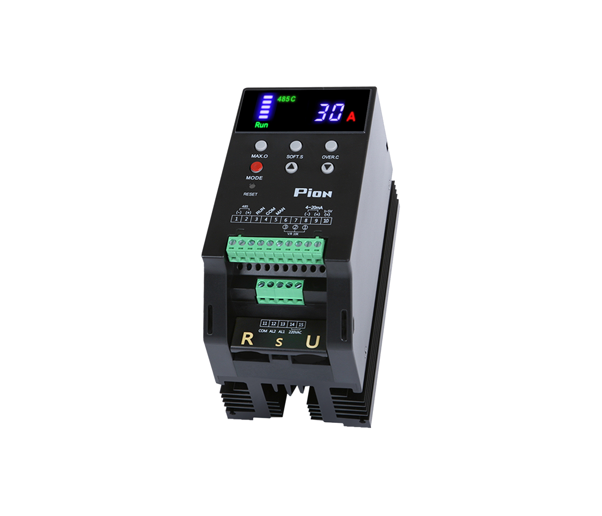
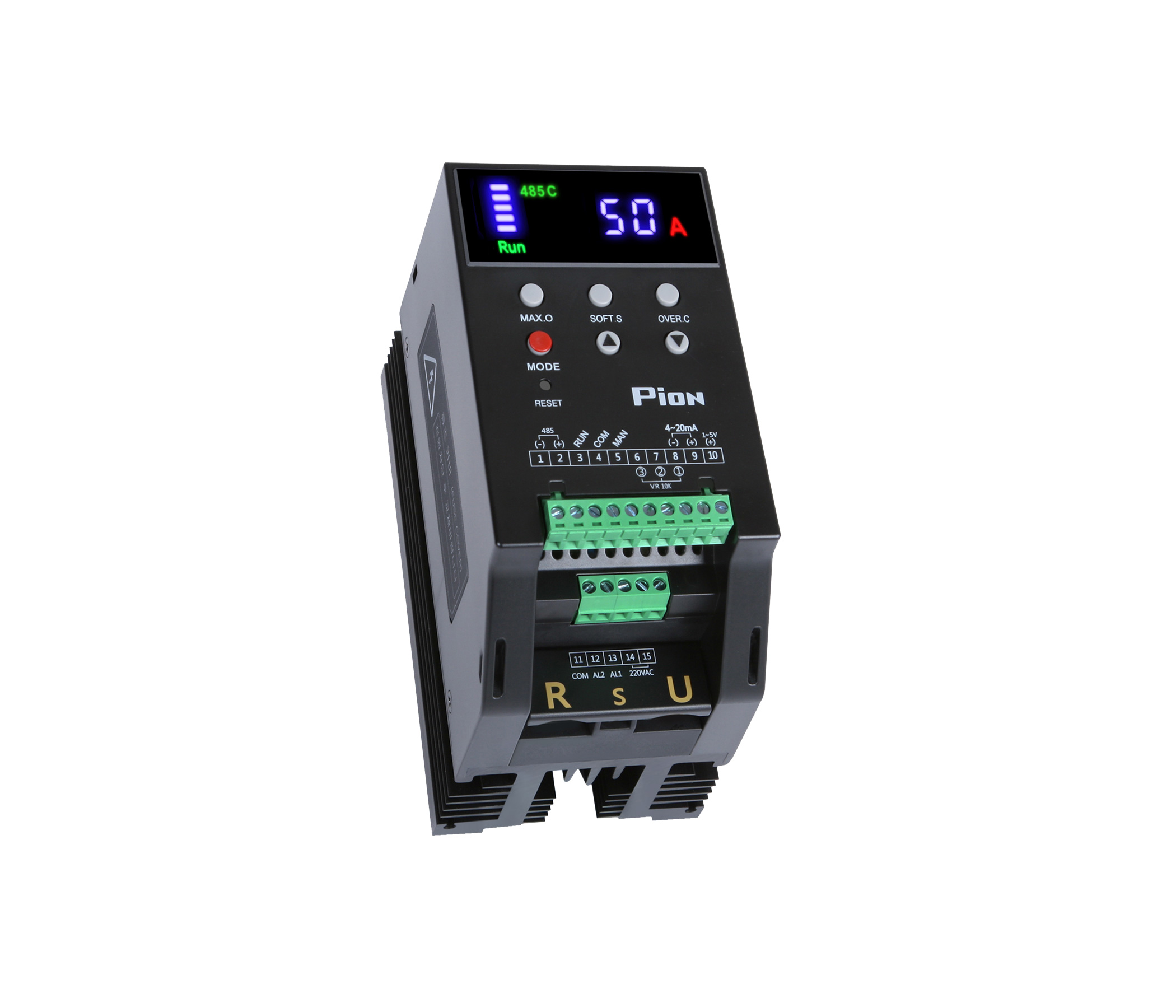
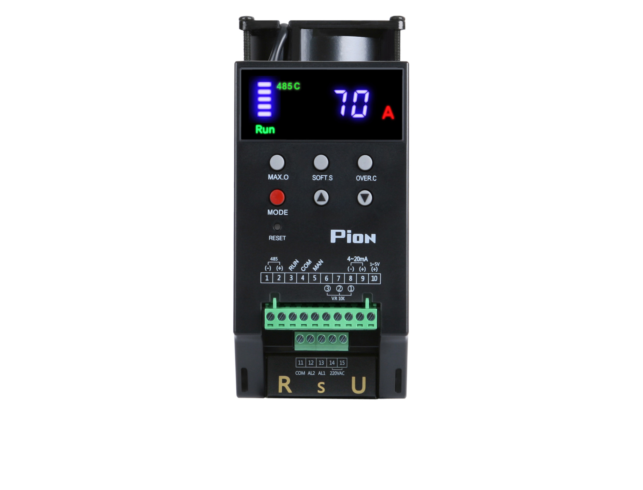
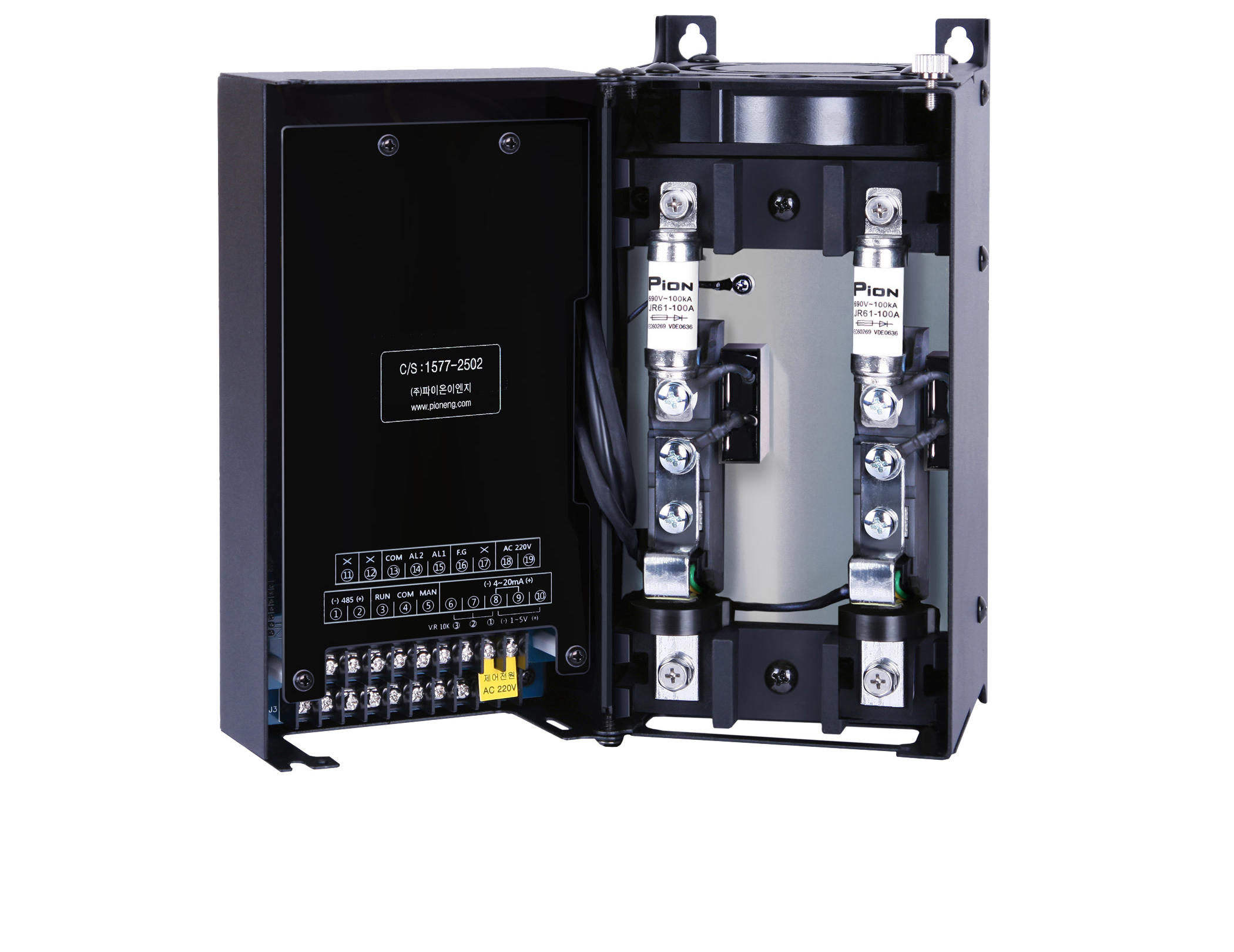
1-Phase 30A / 50A / 70A
A RIGHT THINK FOR QUALITY - PION SERIES
본문
MODEL
PION-D1W-030-xx
PION-D1W-050-xx
PION-D1W-070-xx
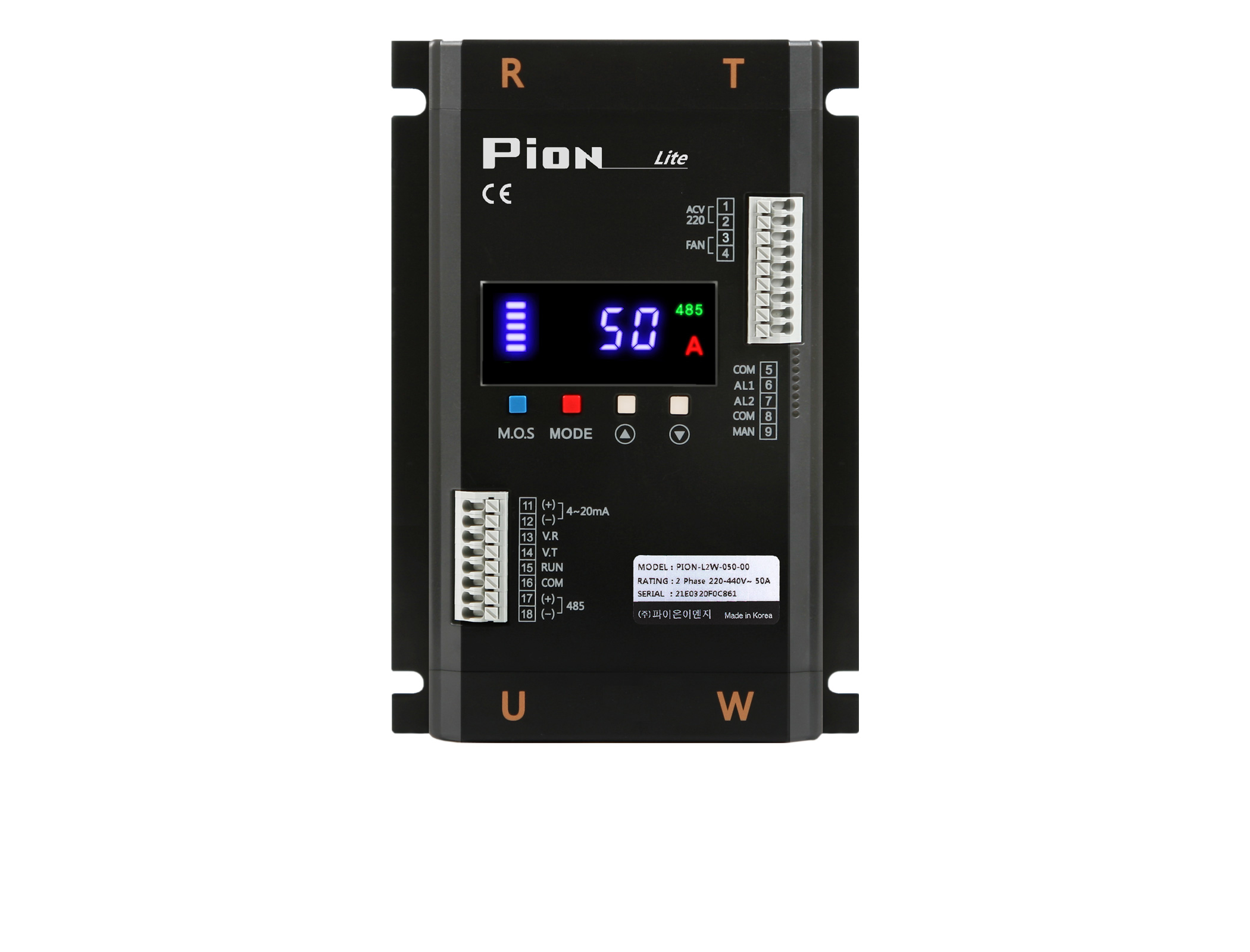
PION-L2W-030-xx
PION-L2W-050-xx
PION-D2W-070-xx
1Leg control (Basic)
MODEL: PION-D1W-xxx-xx
2Legs control (Option)
MODEL: PION-L2W-xxx-xx
MODEL: PION-D2W-070-xx


SPECIFICATION
A RIGHT THINK FOR QUALITY - PION SERIES
For detailed information, please download the "User Manual" below and refer to it.
| CATEGORY | SPECIFICATION | |||
Rated
|
220~440VAC ( MIN 190 ~ MAX 495, R.T Input : Free Voltage - Voltage other than this are made to order) |
|||
Rated
|
30A, 50A, 70A |
|||
Frequency |
50/60Hz (Automatic discriminating) |
|||
Control |
Phase control, Zero crossing control, Combination control (phase + zero crossing) |
|||
Control |
4~20mA, 1~5VDC, 0~5VDC, VR10KΩ, MODBUS (ASCII/RTU) |
|||
Load
|
Heater coupled load (Phase / Zero crossing), Inductive load (Phase) |
|||
Minimum
|
Over 1A |
|||
Output |
0~99% |
|||
Output
|
Signal (4~20mA etc.) control :12Bit
|
|||
Environment |
Humidity : 20~90% (without condensation) Surrounding Air temperature : 0~50℃ |
|||
Cooling
|
30~50A : Natural air-cooling type
|
|||
Dielectric
|
3,000VAC ~50/60Hz for 1 min |
|||
Insulation
|
Power : Case 200MΩ (at 500VDC) |
|||
Control |
110V~230 VAC 50/60Hz
|
|||
Alarm
|
Alarm1, 2 (1a 250VAC 3A) : Over current, Overheating warning, Blown Fuse, Load (Heater) disconnection, |
|||
Basic
|
|
|||
Optional
|
• FAN failure alarm
|
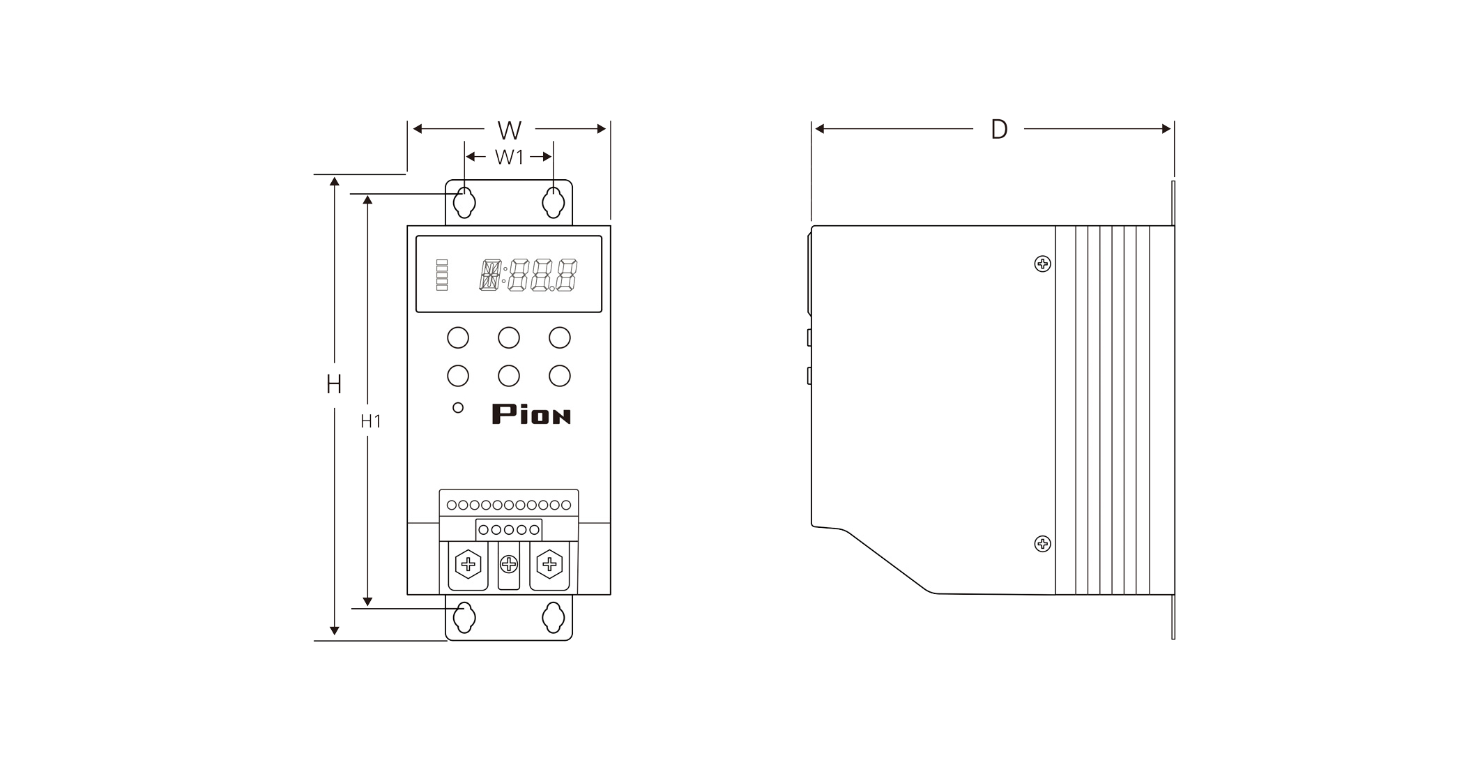
DIMENSIONS - 1leg
A RIGHT THINK FOR QUALITY - PION SERIES
For detailed information, please download the "CAD drawing" below and refer to it.
| Capacity (A) | W | H | D | W1 | H1 | Interval (T) | Weight (kg) | Attachment bolt |
Main Power bolt |
25, 35
|
55 |
135 |
104 |
35 |
117 |
20 |
0.4 |
M4 |
M5/(S)M4 |
30,50 |
80 |
181 |
144 |
35 |
163 |
20 |
2 |
M4 |
M6/(S)M5 |
70 |
80 |
206 |
144 |
35 |
188 |
20 |
3 |
M4 |
M6/(S)M5 |
90 |
115 |
240 |
180 |
93 |
230 |
30 |
4 |
M4 |
M6 |
110,130 |
124 |
282 |
190 |
101 |
270 |
30 |
6 |
M4 |
M6 |
160,200 |
124 |
384 |
207 |
101 |
372 |
30 |
8 |
M4 |
M8 |
250,300 |
166 |
409 |
220 |
143 |
397 |
30 |
11 |
M4 |
M8 |
400,500 |
219 |
510 |
266 |
170 |
490 |
50 |
20 |
M6 |
M10 |
601 |
294 |
570 |
266 |
230 |
550 |
50 |
33 |
M6 |
M12 |
750,850 |
253 |
620 |
330 |
195 |
600 |
50 |
35 |
M6 |
M12 |
| Capacity (A) |
25, 35
|
30,50 |
70 |
90 |
110,130 |
| W |
55 |
80 |
80 |
115 |
124 |
| H |
135 |
181 |
206 |
240 |
282 |
| D |
104 |
144 |
144 |
180 |
190 |
| W1 |
35 |
35 |
35 |
93 |
101 |
| H1 |
117 |
163 |
188 |
230 |
270 |
| Interval (T) |
20 |
20 |
20 |
30 |
30 |
| Weight (kg) |
0.4 |
2 |
3 |
4 |
6 |
| Attachment bolt |
M4 |
M4 |
M4 |
M4 |
M4 |
| Main Power bolt |
M5 / (S)M4 |
M6 / (S)M5 |
M6 / (S)M5 |
M6 |
M6 |
| Capacity (A) |
160,200 |
250,300 |
400,500 |
601 |
750,850
|
| W |
124 |
166 |
219 |
294 |
253 |
| H |
384 |
409 |
510 |
570 |
620 |
| D |
207 |
220 |
266 |
266 |
330 |
| W1 |
101 |
143 |
170 |
230 |
195 |
| H1 |
372 |
397 |
490 |
550 |
600 |
| Interval (T) |
30 |
30 |
50 |
50 |
50 |
| Weight (kg) |
8 |
11 |
20 |
33 |
35 |
| Attachment bolt |
M4 |
M4 |
M6 |
M6 |
M6 |
| Main Power bolt |
M8 |
M8 |
M10 |
M12 |
M12 |
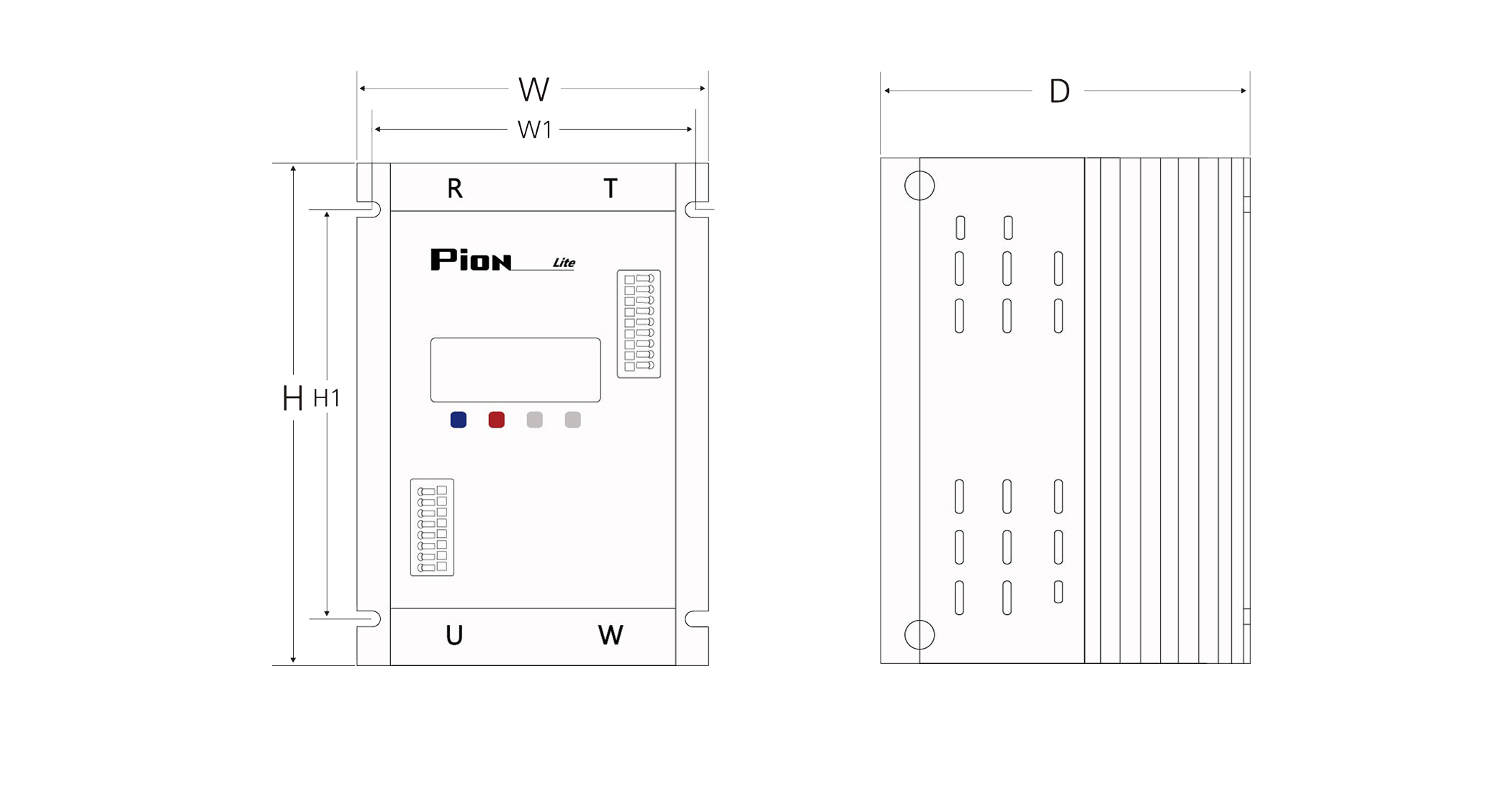
DIMENSIONS - 2legs
PION-L2W-xxx-xx
A RIGHT THINK FOR QUALITY - PION SERIES
For detailed information, please download the "CAD drawing" below and refer to it.
| Capacity (A) | Width (W) | Height (H) | Depth (D) | W1 | H1 | Interval (T) | Weight (kg) | Attachment bolt |
Main Power bolt |
30,50 |
112 |
192 |
166 |
102 |
132 |
10 |
1.9 |
M4 |
M5 |
| Capacity (A) |
30,50 |
| Width (W) |
112 |
| Height (H) |
192 |
| Depth (D) |
166 |
| W1 |
102 |
| H1 |
132 |
| Interval (T) |
10 |
| Weight (kg) |
1.9 |
| Attachment bolt |
M4 |
| Main Power bolt |
M5 |
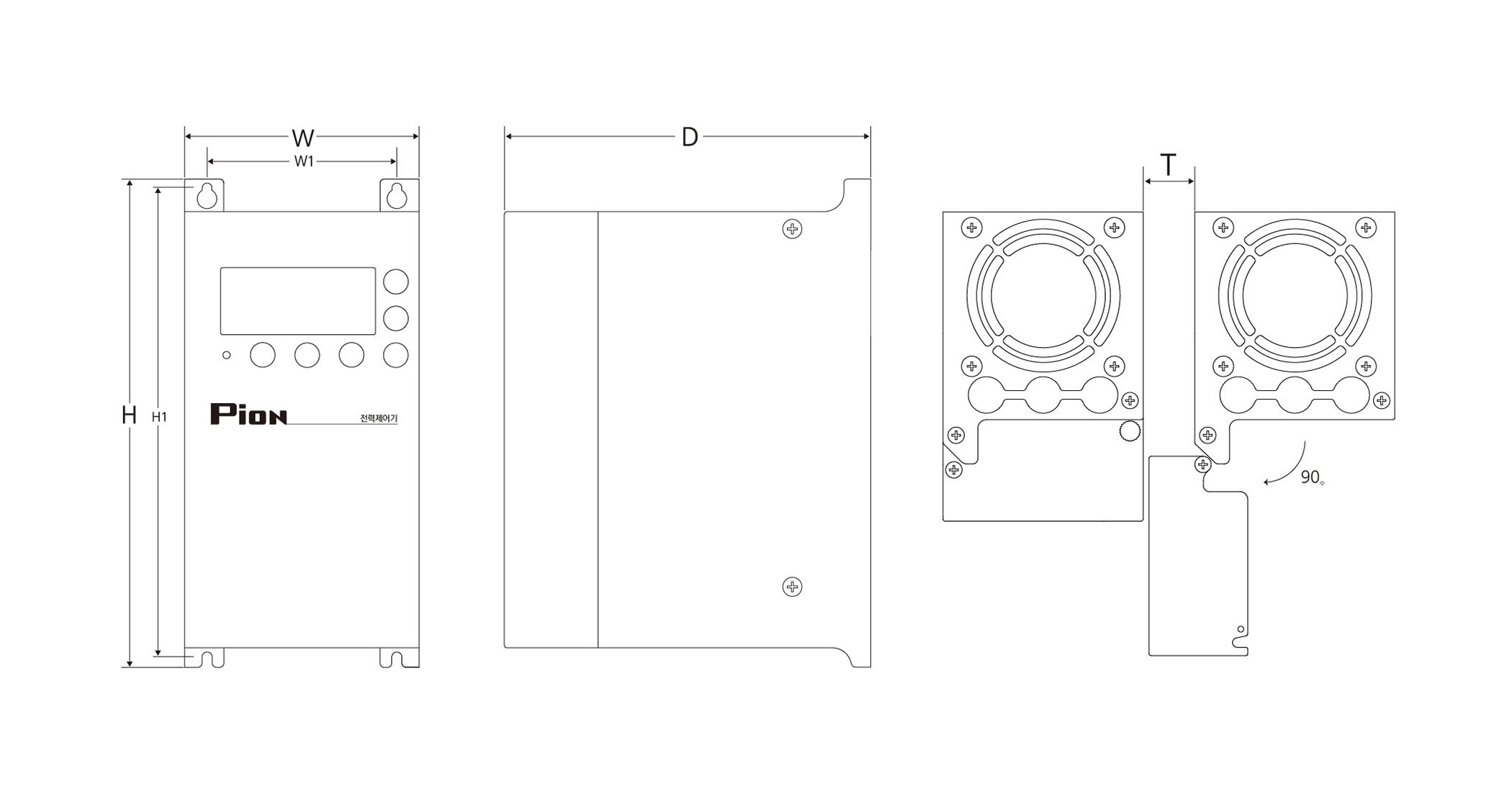
DIMENSIONS - 2legs
PION-D2W-070-xx
A RIGHT THINK FOR QUALITY - PION SERIES
For detailed information, please download the "CAD drawing" below and refer to it.
| Capacity (A) | Width (W) | Height (H) | Depth (D) | W1 | H1 | Interval (T) | Weight (kg) | Attachment bolt |
Main Power bolt |
70 |
115 |
240 |
180 |
93 |
230 |
30 |
4 |
M4 |
M6 |
| Capacity (A) |
70 |
| Width (W) |
115 |
| Height (H) |
240 |
| Depth (D) |
180 |
| W1 |
93 |
| H1 |
230 |
| Interval (T) |
30 |
| Weight (kg) |
4 |
| Attachment bolt |
M4 |
| Main Power bolt |
M6 |
Formula of an electric current amount change According to heater capacity
Actual loading capacity (A) = Result not "x 1.3", Design loading capacity (A) = Result "x 1.3".
Our rated capacity is on condition 25 degrees at room temperature & Rated voltage,
So Please put your
capacity calculation Considering the Field situations (Temperature, Input Voltage etc) when choosing a model.
-
3 Phase
Resistive load=
Heater (W)
× 1.3
1.732 × Voltage
-
3 Phase
Inductive load=
Heater (W)
× 2.0
1.732 × Voltage
-
1 Phase
Resistive load=
Heater (W)
× 1.3
Voltage
-
1 Phase
Inductive load=
Heater(W)
× 2.0
Voltage
[1P 30~70A]Pion English Users Manual_P1NH3_Rev_10.pdf (2.8M)
[2D_CAD] 1P_PION_1Leg_2Legs_25A~1200A Rev09.dwg (52.6M)
[3D_CAD] 1P[1Leg] PION-D1W_030~1200, 2P[2Legs] PION-D2W-030~1200A Rev02.zip (152.8M)