
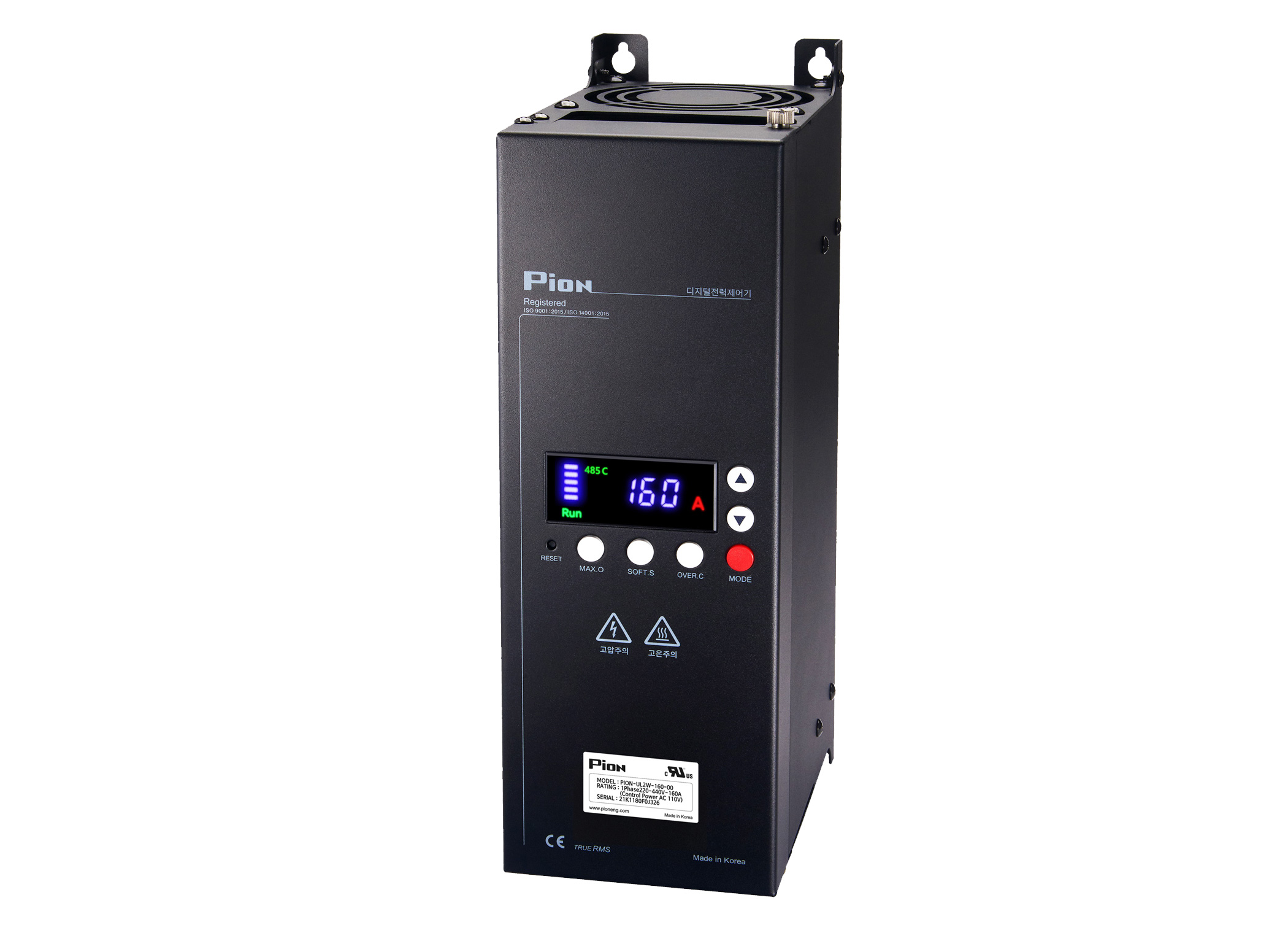
[UL] 1-Phase 30A~500A (2Legs)
A RIGHT THINK FOR QUALITY - PION SERIES
본문
MODEL
PION-UL2W-030-□□,-040-□□
-050-□□,-060-□□
-070-□□,-090-□□
-110-□□,-125-□□
-130-□□,-150-□□
-160-□□,-200-□□
-250-□□,-300-□□
PION-UD2W-400-□□,-500-□□

SPECIFICATION
A RIGHT THINK FOR QUALITY - PION SERIES
For detailed information, please download the "User Manual" below and refer to it.
| CATEGORY | SPECIFICATION | |||
Rated
|
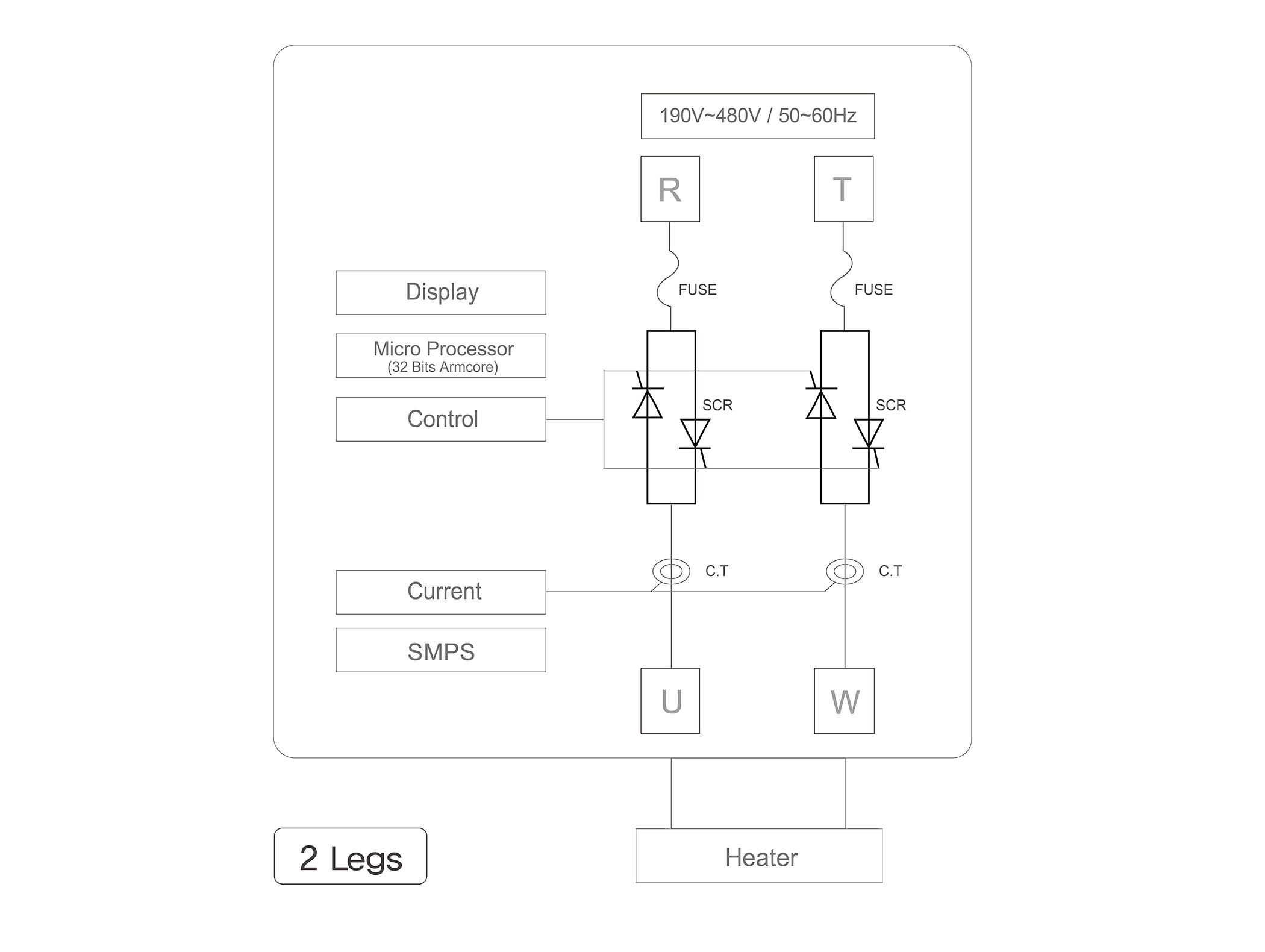
190~480VAC (R.T Input : Free Voltage) |
|||
Rated
|
30, 40, 50, 60, 70, 90, 110, 125, 130, 150, 160, 200, 250, 300, 400, 500(A) |
|||
Frequency |
50/60Hz (Automatic discriminating) |
|||
Control |
Phase control, Zero crossing control, Combination control (phase + zero crossing) |
|||
Control |
4~20mA, 1~5VDC, 0~5VDC, 0~10VDC, VR10KΩ, MODBUS (ASCII/RTU) |
|||
Load
|
Heater coupled load (Phase / Zero crossing), Inductive load (Phase) |
|||
Minimum
|
More than 1A |
|||
Output |
0~99% |
|||
Output
|
Signal (4~20mA etc.) control :12Bit
|
|||
Environment |
Humidity : 20~90% (without condensation) Surrounding Air temperature : 0~50℃ |
|||
Cooling
|
Forced air cooling type
|
|||
Dielectric
|
3,000VAC ~50/60Hz for 1 min |
|||
Insulation
|
Power : Case 200MΩ (at 500VDC) |
|||
Control |
110VAC 50/60Hz
|
|||
Alarm
|
Alarm1, 2 (1a 250VAC 5A) : Over current, Overheating warning, Blown FUSE, Load (Heater) disconnection,
|
|||
Basic
|
|
|||
Optional
|
• Current limit (voltage feedback)
|
DIMENSIONS
A RIGHT THINK FOR QUALITY - PION SERIES
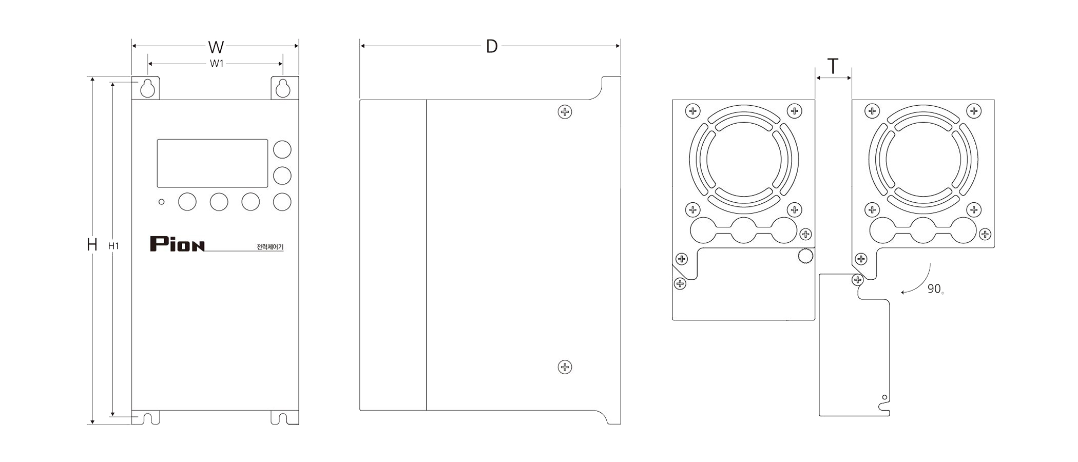
For detailed information, please download the "CAD drawing" below and refer to it.
For UL1W-030,050,070 models, the dimension of H1 will be changed to "188 → 225.5 mm" when using the voltage/power feedback option. (Refer to CAD drawing)
| Capacity (A) | W | H | D | W1 | H1 | Interval (T) | Weight (kg) | Attachment bolt |
Main Power bolt |
Remarks | |
Single |
30,40,50 |
115 |
240 |
180 |
93 |
230 |
30 |
4 |
M4 |
M6 |
Fig.2 |
60,70,90,
|
124 |
282 |
190 |
101 |
270 |
30 |
6 |
M4 |
M6 |
||
150,160,
|
124 |
384 |
207 |
101 |
372 |
30 |
8 |
M4 |
M8 |
||
250,300 |
166 |
409 |
220 |
143 |
397 |
30 |
11 |
M4 |
M8 |
||
400,500 |
294 |
570 |
266 |
230 |
550 |
50 |
38 |
M6 |
M12 |
Single Phase (2Legs) |
|||||
| Capacity (A) |
30,40,50 |
60,70,90,
|
150,160,200 |
250,300 |
400,500 |
| W |
115 |
124 |
124 |
166 |
294 |
| H |
240 |
282 |
384 |
409 |
570 |
| D |
180 |
190 |
207 |
220 |
266 |
| W1 |
93 |
101 |
101 |
143 |
230 |
| H1 |
230 |
270 |
372 |
397 |
550 |
| Interval (T) |
30 |
30 |
30 |
30 |
50 |
| Weight (kg) |
4 |
6 |
8 |
11 |
38 |
| Attachment bolt |
M4 |
M4 |
M4 |
M4 |
M6 |
| Main Power bolt |
M6 |
M6 |
M8 |
M8 |
M12 |
| Remarks |
Fig.2 |
||||
Formula of an electric current amount change According to heater capacity
Actual loading capacity (A) = Result not "x 1.3", Design loading capacity (A) = Result "x 1.3".
Our rated capacity is on condition 25 degrees at room temperature & Rated voltage,
So Please put your
capacity calculation Considering the Field situations (Temperature, Input Voltage etc) when choosing a model.
-
3 Phase
Resistive load=
Heater (W)
× 1.3
1.732 × Voltage
-
3 Phase
Inductive load=
Heater (W)
× 2.0
1.732 × Voltage
-
1 Phase
Resistive load=
Heater (W)
× 1.3
Voltage
-
1 Phase
Inductive load=
Heater(W)
× 2.0
Voltage
FILE : UL_[1P 1Leg 90~500A 2Legs 30~500A]Pion Users Manual_P1CF9_Rev_10.pdf (5.9M)
FILE : [2D_CAD] UL_1P_PION_1Leg_2Legs_30A~500A Rev07.dwg (12.1M)
FILE : [3D_CAD] UL 2P[2Legs]_PION_UL[D]2W_30~500_Rev01.zip (35.7M)